Welcome to
Young's Photo Gallery
James W. Young, Professional Photographer
Photographic History of Table Mountain
Observatory
Part 6: Larger Optical Telescopes, Optical Programs Expand
Section A
By James W. Young
retired astronomer from Table Mountain Observatory
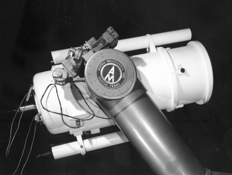
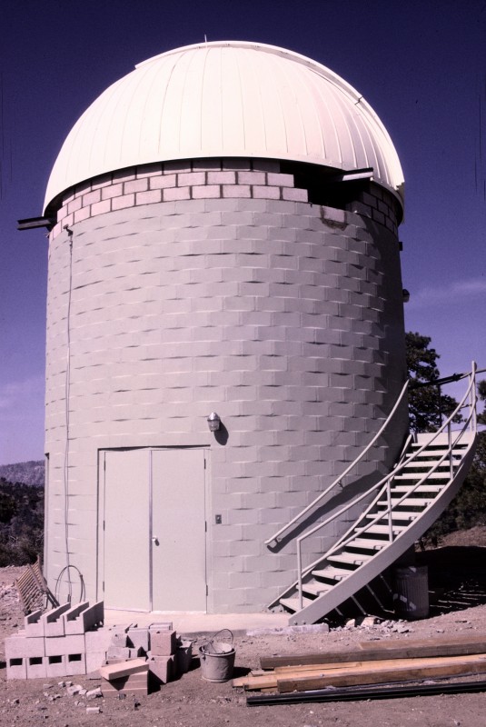
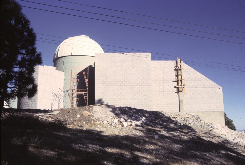
The new Astro Mechanics 24-inch f/16/36 Cassegrain/Coude Telescope
Building number TM-12
Another new telescope building is finished, an 'Ash Dome' was installed on the top edge,
and another newly purchased telescope is installed. Follow along with the history of this
new professional grade instrument and science achievements....
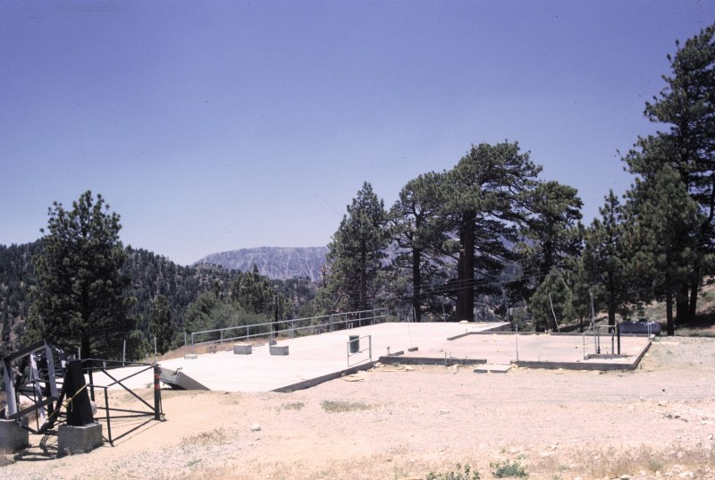
The Butler Building (TM-2) was removed in preparation for the new telescope building for
the 24-inch telescope.
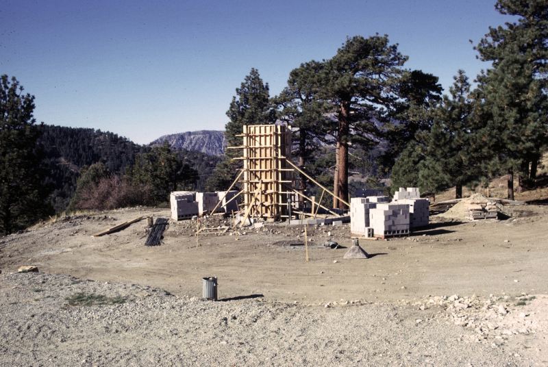
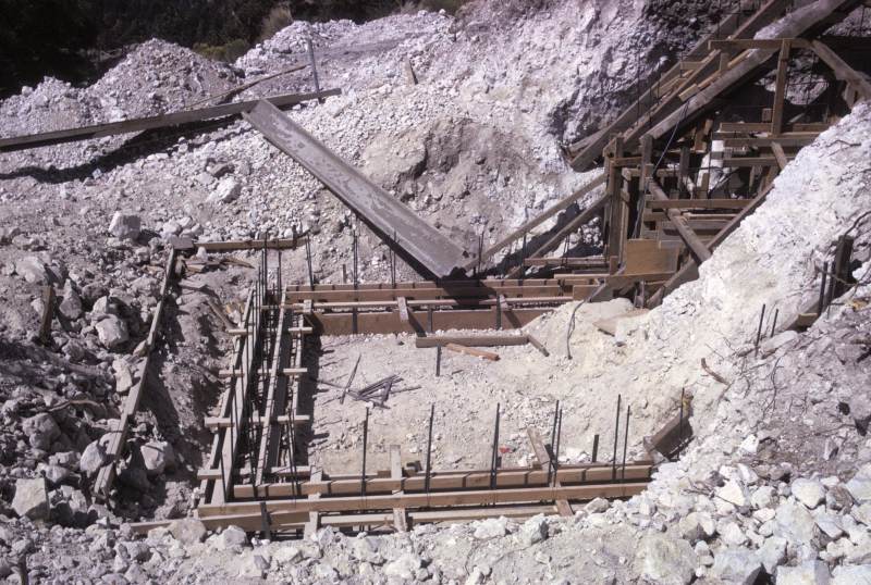
The foundation and forms for the large telescope pier were made in October 1965, almost
exactly where the old Butler Building had been earlier.
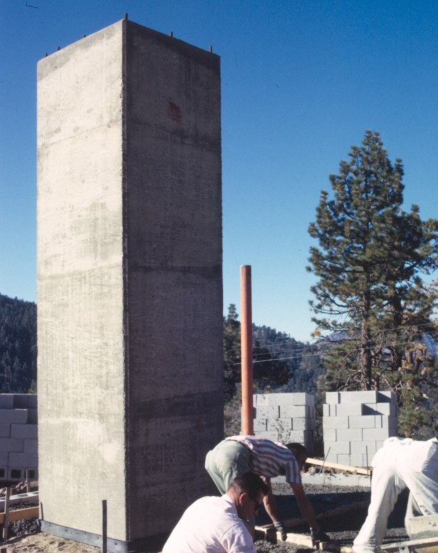
The concrete pier was 19 feet underground, and 15 feet above ground!

The outside block wall of the 20-foot diameter building was specifically made for a new
24-foot diameter Ash Dome to be delivered later. November 1965
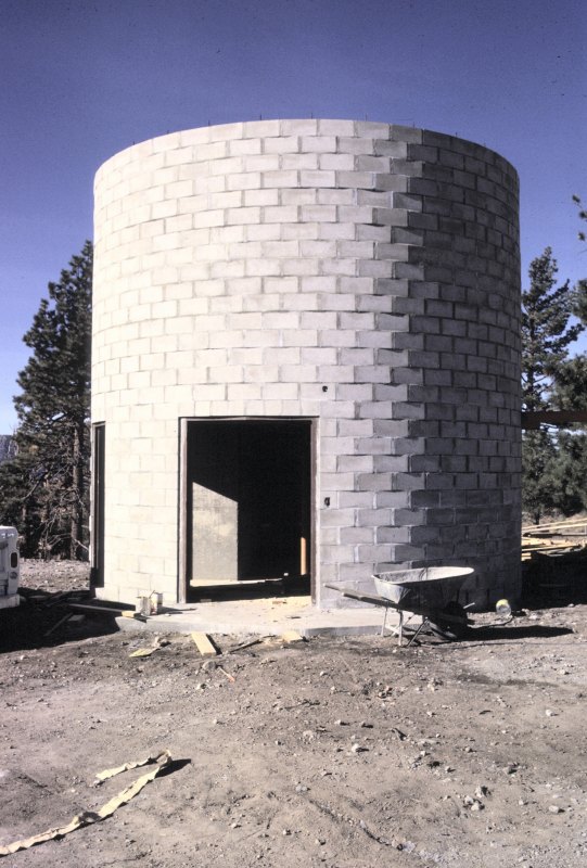
The finished block wall the middle of November 1965
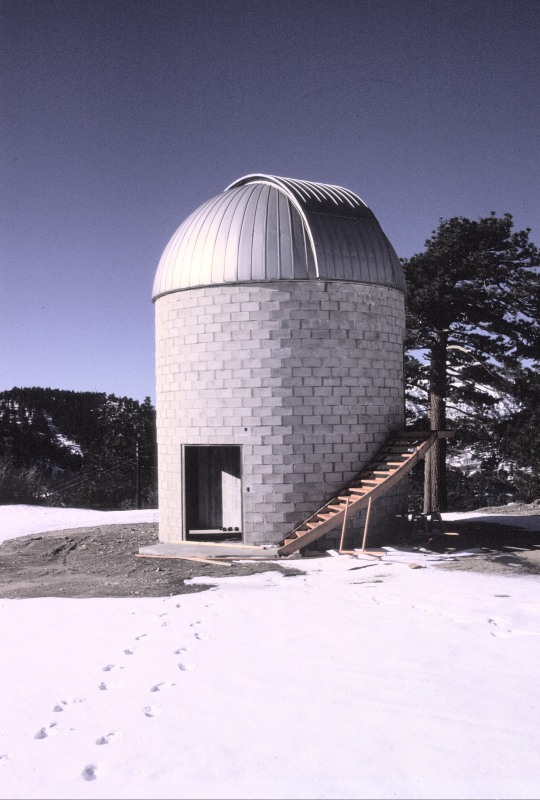
In late November, Ole Olson and his Ash Dome crew from Illinois drove to Table Mountain
with dome pieces on a flat-bed truck. Ole hired Jack Lyon and the author over a weekend
to help construct the dome in two days. Here is the finished dome in early December 1965.
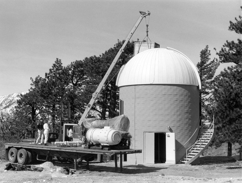
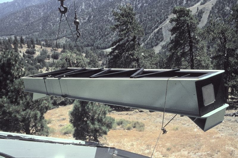
In March 1966, Astro Mechanics arrived with the new 24-inch Cassegrain/Coude telescope.
JPL paid an amazing $68,000 for the instrument.
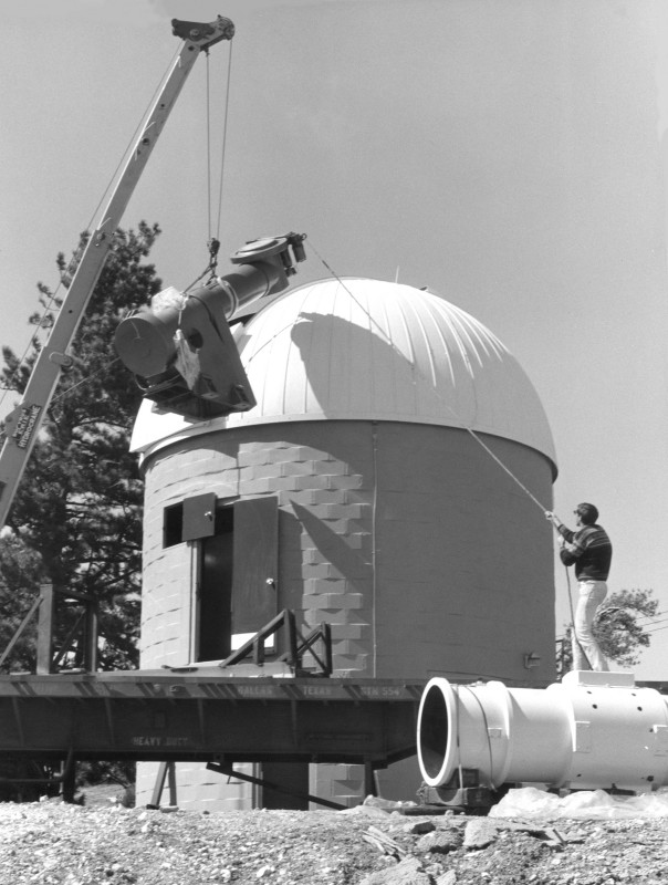
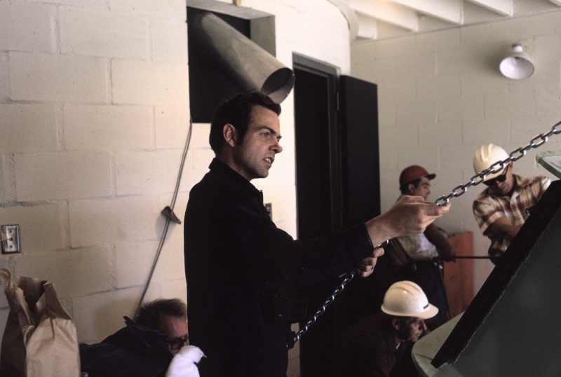
Lowering the large asymmetric telescope mount into the building
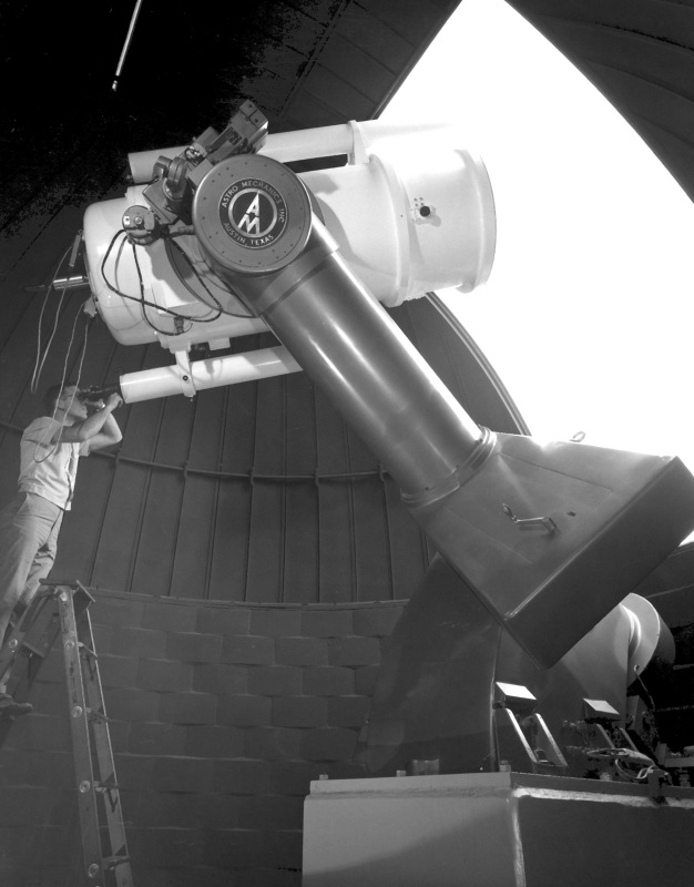
The author standing near the top of a 12-foot ladder to pose for the JPL photographer.
Interestingly enough, after the building, dome, and telescope were signed off, JPL was
able to add a new raising floor utilizing a hydraulic ram piston with an oil reservoir tank.
Observations could be made by raising/lowering the movable floor as needed, along with
a small portable ladder when necessary. Note that the telescope is on the east side of
the polar axis...a change later described...
The delivered instrument had the telescope tube on the east side of the polar axis, which
later proved not a good choice. The auther proposed to change that...see more later.
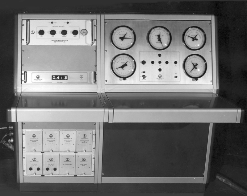
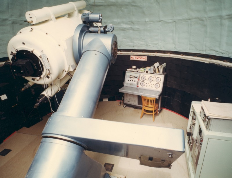
The analog operational telescope control console
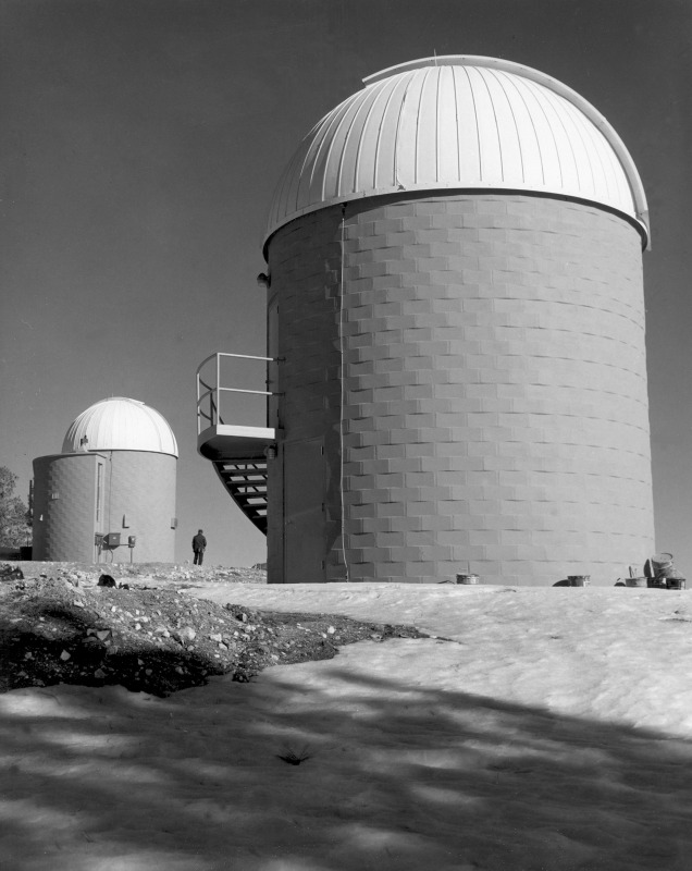
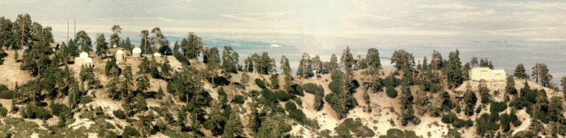
Late Spring in 1966, with the 16-inch telescope building in the background
We found out that no one is perfect, even the engineers that designed the building. With
an asymmetric mounting, the telescope would not clear the top inside of the dome when it
was pointing at the zenith! Because the telescope tube was not in the center, JPL had to
scramble to raise the already installed Ash Dome. Contractors added three more rows
of blocks, and then lowered the dome back onto the wall. A little embarrassment!
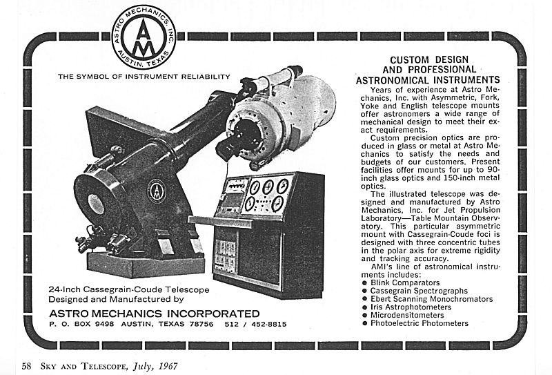
A very nice advertisement in Sky and Telescope Magazine in July 1967.
JPL constructed the major additions to TM-12; the coude room, darkroom, and restroom
in September 1967. The above image is of the coude room construction area.
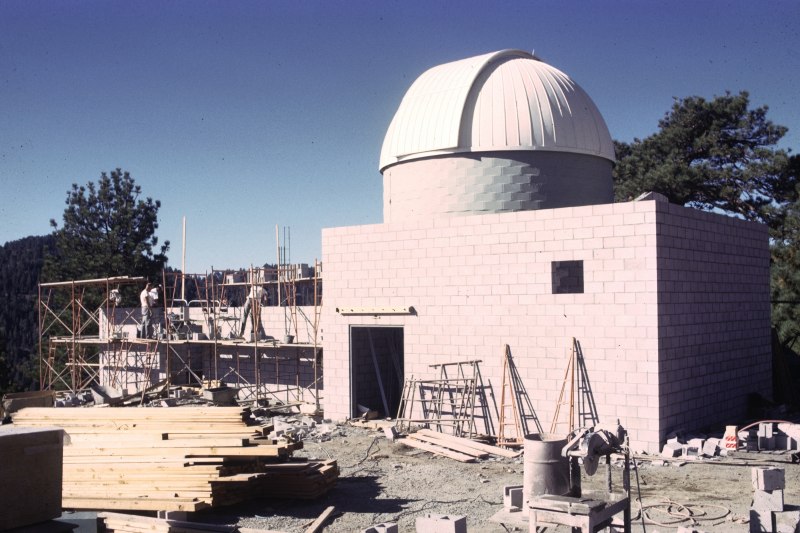
The new coude room (left) and darkroom additions (right) in September 1967
View of the coude room expansion (right of the dome section)
Here are the many programs, people, and instruments used with the
24-inch telescope...both in Cassegrain and Coude modes.
This is the Harvey Mudd photometer, used by Sandy Sandmann on the 16-inch telescope,
but adapted to the 24-inch. Sandmann used this instrument to continue his research of
cepheid variable stars with the 24-inch telescope. This instrument was also used by Ellis
Miner (a new JPL astronomer) and Young to study the potential brightening of Saturnian
satellites as they emerged from Saturn's shadow, as well as whether Saturn's satellites
could be tidally locked to the planet. This was in 1966-67.
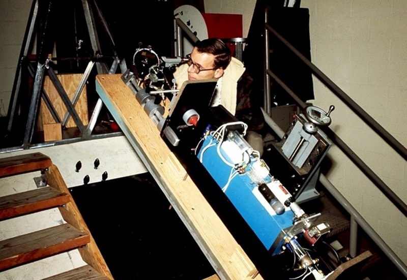
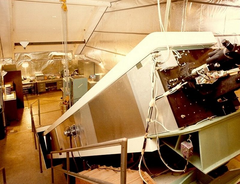
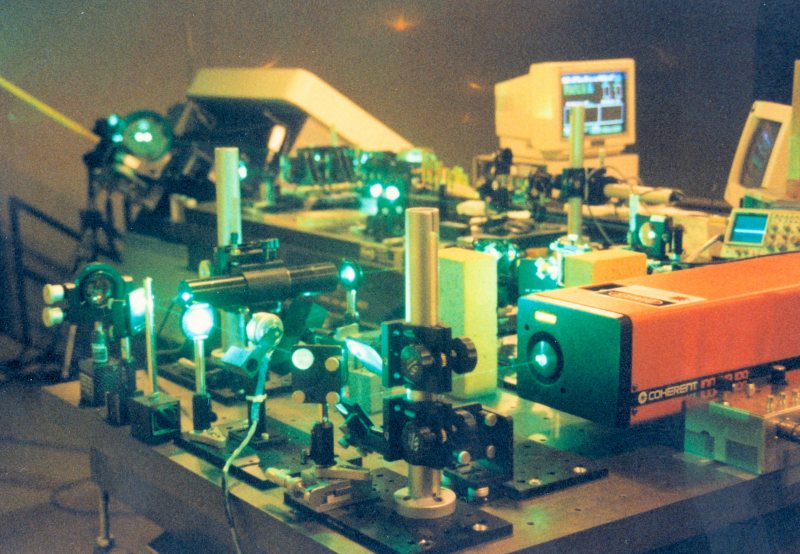
In December 1967, Mike Shumate of JPL proposed an experiment of pointing a laser beam
to the Surveyor VII Spacecraft on the Moon. The above image shows the author sitting at
the coude telescope control position, with the newly designed experimental Hughes Aircraft
2-watt argon laser (the blue box) a week before the test in January 1968.
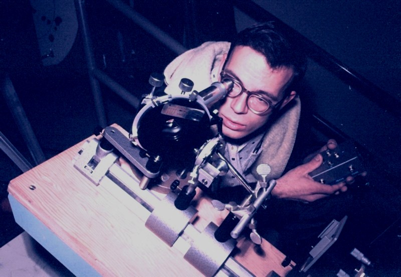
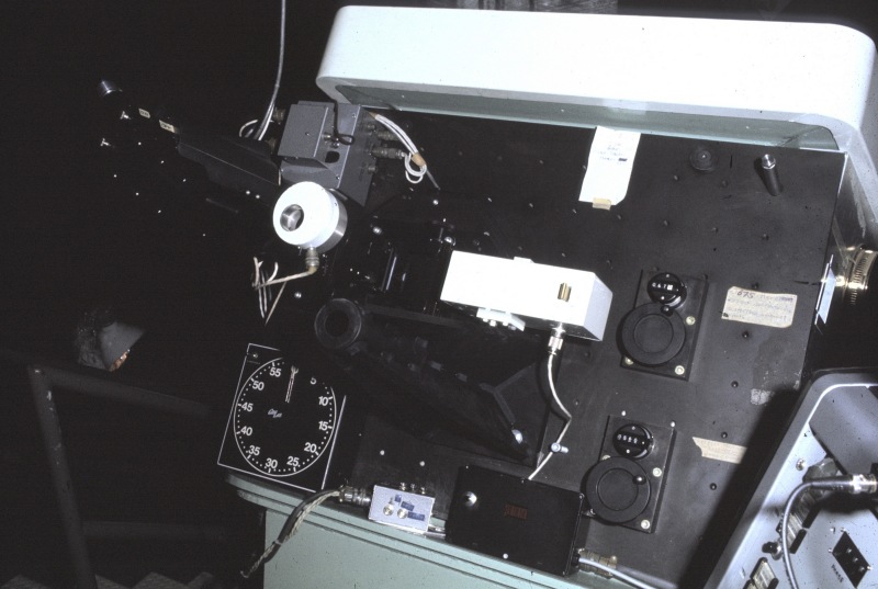
Here, the author is viewing the image of the Moon reflected off a 45-degree angled mirror
with a hole in the center. The outgoing laser beam passed through the hole from the blue
box (off to the lower right), and up into the telescope. An expanding lens, just right of the
angled mirror housing, matched the telescope's focal length to collimate the laser beam as a
24-inch diameter parallel beam aimed at the Moon...
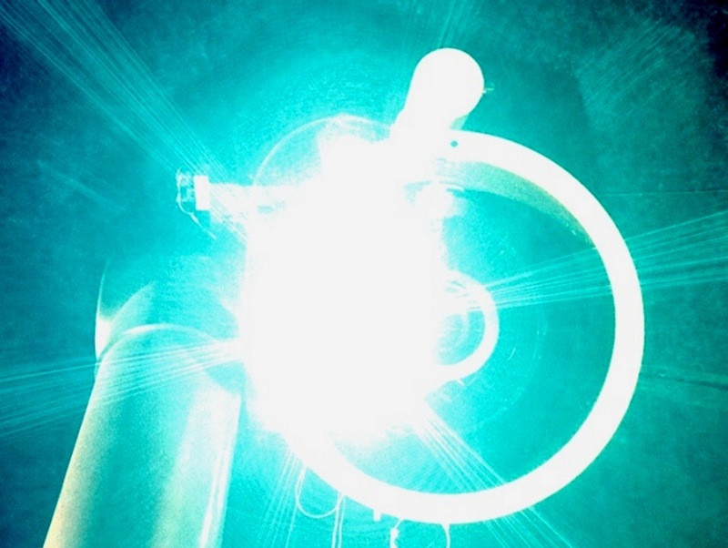
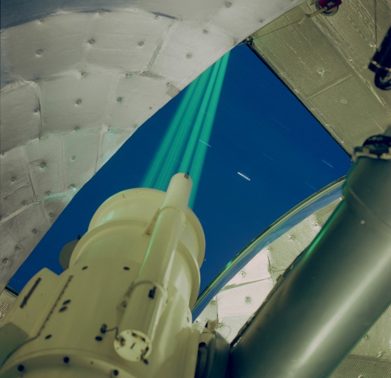
This is the high intensity argon laser beam leaving the 24-inch telescope, as a parallel light
source aimed at the position of the Surveyor VII Spacecraft on the Moon. To put this into
into perspective, this picture was taken with a 35mm camera using a lens at f/16 about 1/16
of an inch in diameter. This 1/16-inch lens aperture hole is an extremely small part of the
larger 24-inch diameter beam, or about 0.001% of the entire laser beam.
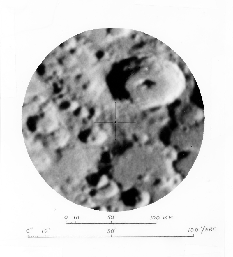
This is an image of the lunar crater Tycho (upper right), with a dot and crosshair marking
the spot where the Surveyor Spacecraft was located......and where the author aimed the
telescope with the laser beam...
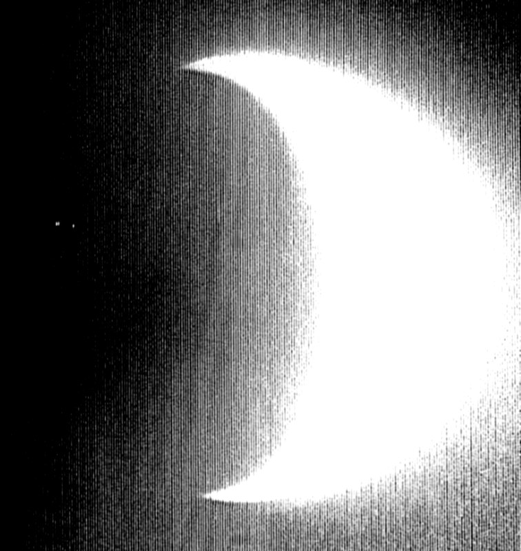
This is an image taken by the Surveyor VII spacecraft of the bright crescent Earth
(as recorded back at JPL's Goldstone facility) showing spots in the upper left center.
The single fainter spot is the beam coming simultaneously from Kitt Peak Observatory's
setup in Arizona. The double spot just to the left of Kitt Peak is Table Mountain, as
a brighter image seen from the Moon, affected two scan lines (producing two spots),
rather than only the one seen from Kitt Peak's setup.
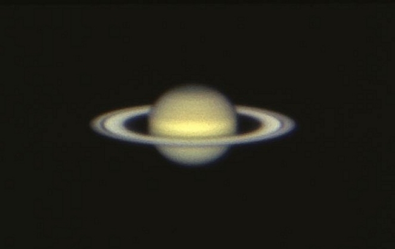
Capen and Young continued the photographic and visual patrols of Venus, Mars, Jupiter, and
Saturn. This image of Saturn was taken in 1968 under excellent seeing conditions.
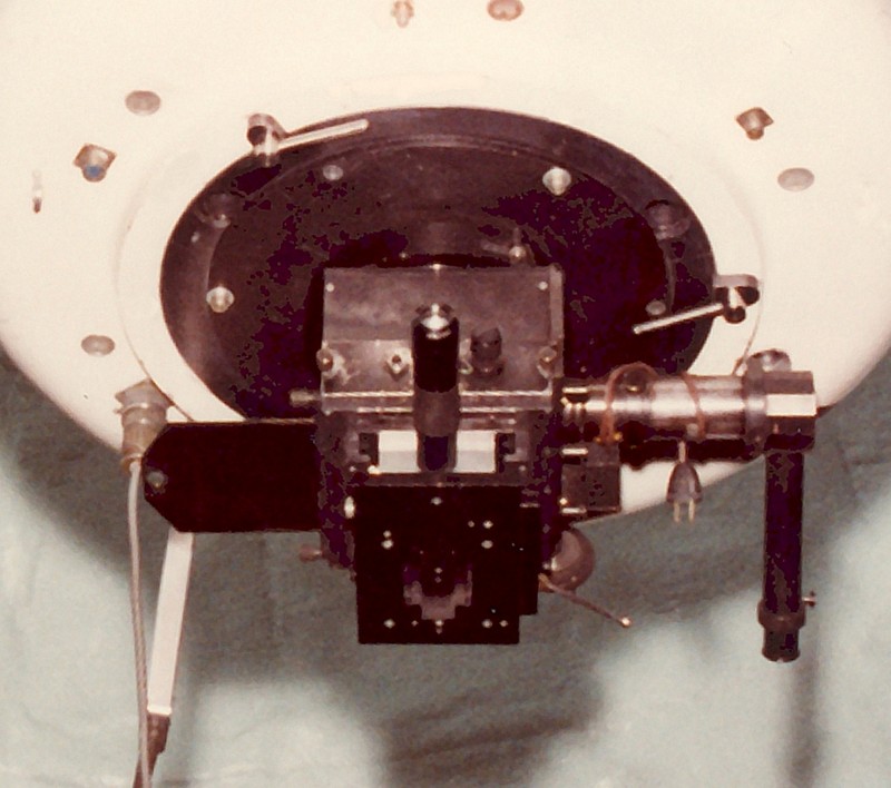
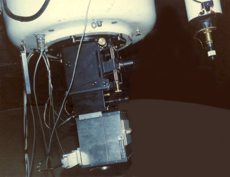
A new JPL astronomer, James Gunn, had this Cassegrain camera built specifically for both
photographic and photometric observations. It was designed to use Kodak 4x5 glass plates
for photography, as well as to hold a newly acquired Mt. Wilson-designed photometer. In
this image, the photometer head is held in the same slot where the photographic plates are
used. The shutter slide permitting the telescope's beam for either the plate photography
or the photometric operation is open to the left. The angled lever at the lower right can
be manually moved by the observer for necessary filter changes.
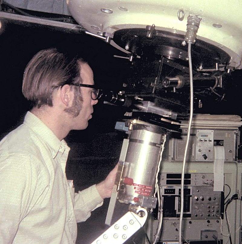
The complete photometer, with the Mt. Wilson cold box (packed with dry ice) attached to
the filter, aperture, beam splitter, and eyepiece portion built by Gunn. Above, the author
is viewing with the eyepiece to center the desired object before moving the beam splitter
to allow the light path to enter into the cold box and onto the ASCOP photomultiplier tube.
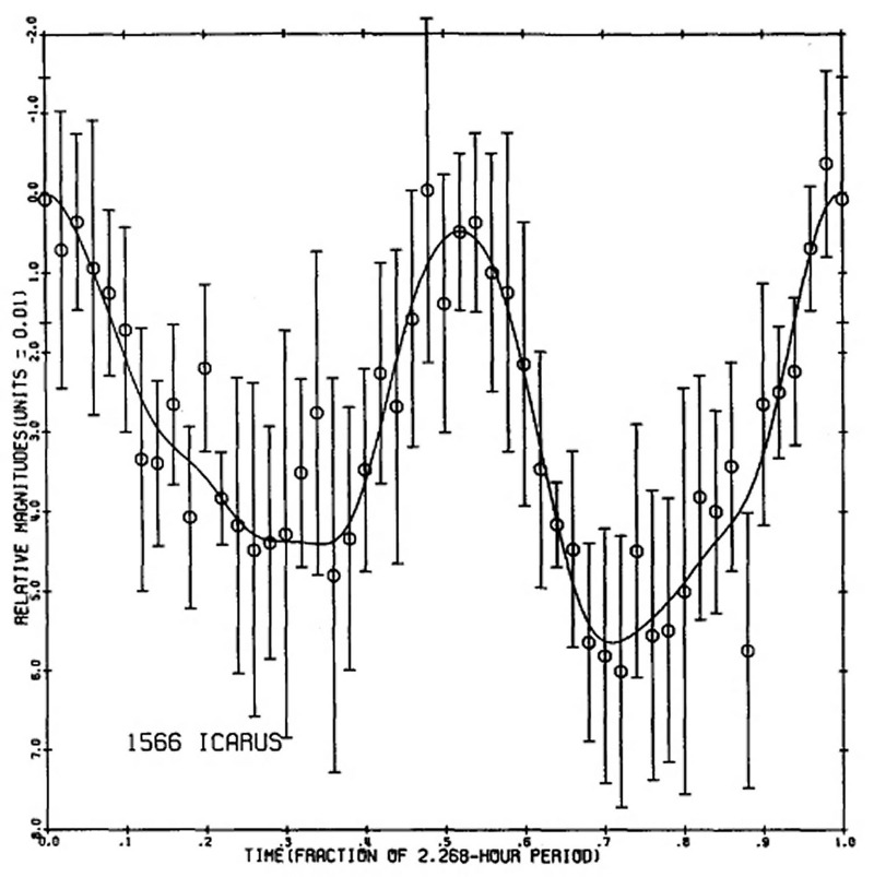
The processed data from the asteroid 1566 Icarus' light variation due to its rotation, was
obtained by Ellis Miner (another JPL astronomer) and Young in June 1968, with the results
published in the ICARUS journal in 1969...the first publication of its kind showing science
results from the new 24-inch telescope and its associated instrumentation.
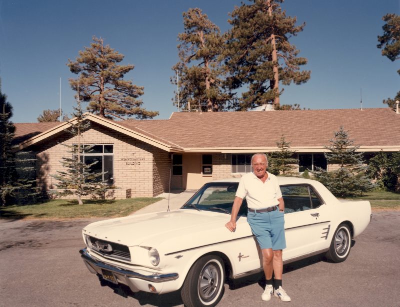
This is Frank Chase, with his custon built 1966 Ford Mustang, at Table Mountain. Chase
was made a volunteer Research Affliate (RA) for JPL, and gave considerable assistance
to visiting astronomers, as well as to the author for over 20 years. Chase and the author
used the coude spectrograph to produce a telluric line atlas of spectra lines from 580 nm
into the IR at 1100 nm. This atlas provided spectrometrists a reference spectrum to use
for any necessary comparisons in their individual research programs.
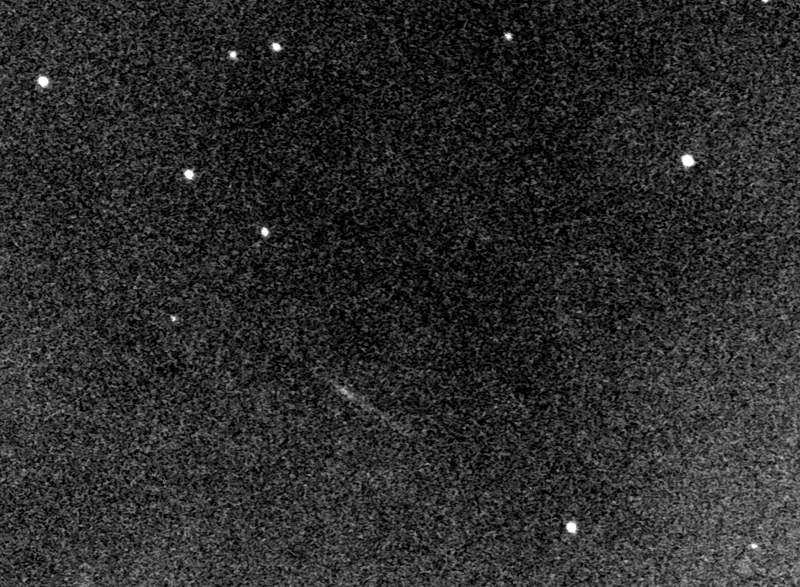
In December 1968, Young photographed the Apollo VIII spacecraft (streak at left center)
200 km from the earth, using the Cassegrain camera and a Kodak 4x5 IIa-D glass plate.
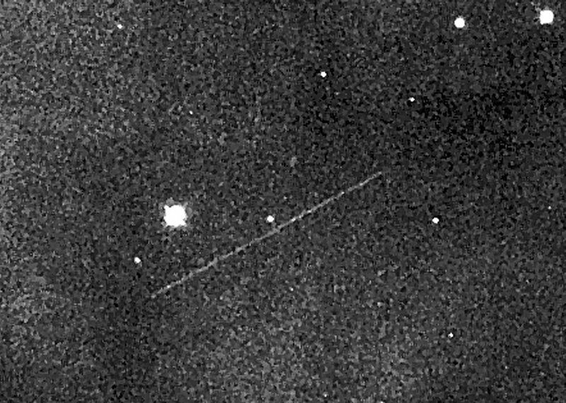
Apollo XI returning from the moon on July 23, 1969, also as photographed by Young using
the Cassegrain camera.
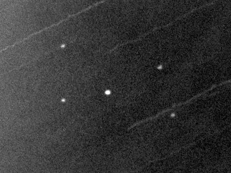
Apollo XIII, as photographed on April 12, 1970 by Young. The CSLM (Command Service
& Lunar Modules) is the center object. The four additional objects are the expended SLA
(Spacecraft-LM Adapter) panels that were deployed from the S-IVB to expose the LM
(Lunar Module). The CSM (Command & Service Module) then docked with the LM, and then
continued toward the moon. This was a day before the Service Module accident.
Along with the Cassegrain camera, Gunn also had a 1-meter Ebert-Fasti spectrometer built
that used the Mt. Wilson photometer for recording the data. During 1968-69, Gunn was
joined by another JPL astronomer, Hyron Spinrad as well as the author, in researching the
color changes and absorption line variations in the Andromeda Galaxy using this instrument.
Their scientific results were published in the 1971 Astrophysical Journal, volume 164.
After a few years using the 24-inch telescope, the author proposed a major change to the
telescope. When delivered in 1966, the telescope tube assembly tracked west up and over
the polar axis mount as it pointed west. While observing to the east, the telescope was low
on the underside of the polar axis preventing the user from seeing objects low in the east.
Young checked the specific drawings provided by the builder, Astro Mechanics, of the cable
wraps inside the axis (accessible though two portholes in the base of the telescope mounting).
Re-arranging the cables, Young 'flipped' the pier, allowing the telescope to see the eastern
horizon, with a loss of the western horizon. BUT, the eastern horizon was clear of treetops,
and the western horizon was blocked by numerous trees. It was a win-win situation, as shown
in the above image looking north, with west to the left, and east to the right.
The newly constructed coude spectrograph frame (built entirely at JPL) being delivered to
the coude room in 1969. The spectrograph frame is 30 feet long, and was made to house
the collimating mirror, the 14-inch square blazed grating, and a 24-inch long photographic
curved glass plate holder.
Robert Norton, the director of the astronomy group, assigned to Table Mountain, is seen
here helping to install the spectrograph's (seen in the lower right edge of this image)
final resting place on three special anchor installation pins.
The 30-foot long Coude Spectrograph, made at JPL, housed a 14-inch collimating mirror, a
14-inch blazed (in third order) grating with 316 lines/mm, and a 24x48-inch camera mirror
that allowed a 20-inch wide spectrum to be recorded on (2) Kodak glass 1.3x10-inch glass
plates. A second grating, blazed in fourth order, for better IR coverage of the spectrum
could be used as needed. Resolution in 3rd order was 2.1 A/mm, and 1.7 A/mm in the 4th
order. At the time, this was the world's largest planetary spectrograph!
Top of the spectrograph with the auto-guider and image stabilizer (white circle with lens)
at the top left, the neon-line calibration lamp housing (center rectangular box), focus and
grating position and readout controls (right center), and the exposure counter in the rack
in the far lower right. The observed planetary image (Venus, Mars, Jupiter, Saturn, or
Uranus) entered the slit jaw (not seen in this picture). The image spill-over was easy for
for the auto-guider to keep a planet's image properly centered on the slit during any
necessary exposure. Before the auto guider was installed, guiding was done manually by
the observer using the paddle seen on the bottom spectrograph ledge (bottom center).
The longest manually guided image was 8 hours by JPL astronomer Ray Newburn and
the author while exposing Saturn in the 645 nm band. Each observer guided one hour
on, then one hour off...repeated for 8 hours.
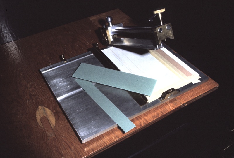
Another Mt. Wilson product: a Kodak glass plate cutter acquired for Table Mountain. It
was used to cut spectrographic plates (for different wavelengths) 1.33 inches wide, from a
delivered 4x10-inch Kodak box of 12 plates. One or two plates could be used in the plate
holder for the spectrograph, depending upon the width of the band(s) the observer wanted.
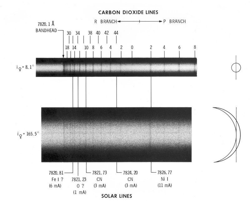
JPL astronomers Andrew Young, Louise Young, Jay Bergstralh, and the author spent nearly
2 years observing Venus during both superior and inferior conjunctions in the 781 nm and
869 nm carbon dioxide bands. This study of the apparent strength of CO2 absorption in
the spectrum of Venus revealed a 4-day period. Spectra were obtained on Kodak IV-N
hypersensitized plates produced by the author in the telescope's darkroom.
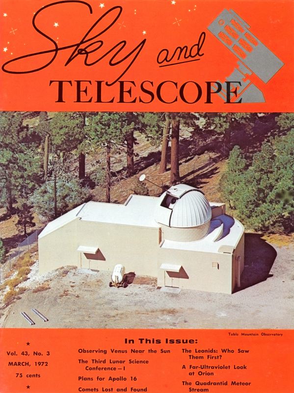
A little press never hurt anyone! This Sky and Telescope March 1972 issue shows the
sunscreen devised to block the sun for the Venus observations. The round white disk was
moved up/down and left/right by controlling the dome shutter (up or down) and the dome
rotation (left or right).
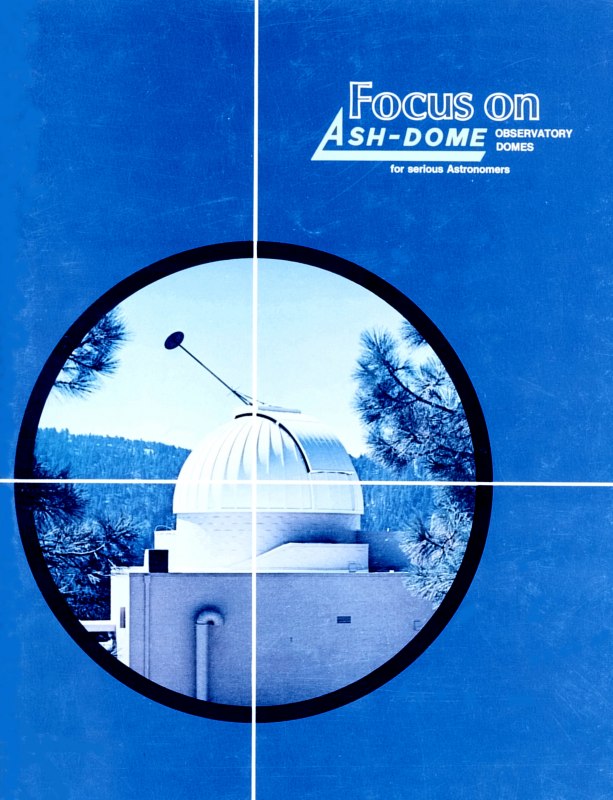
Even Ash Dome got into the action with one of their brochures showing the sunscreen
attached to one of their domes at Table Mountain!
There were several other instruments related to the use of the coude spectrograph
through the 1970s. Many JPL astronomers chose specific measuring devices in their
particular research programs while using the spectrograph. Reinhard Beer developed
his own Connes-type interferometer to study Mars in the near infrared from 3 to 4
microns. Frank Chase donated his own image intensifier tube (IIT) for others to use
in their study of ammonia and methane lines in both Jupiter and Saturn. Eventually
a new S-25 ITT was used successfully by Jack Margolis, Jay Bergstralh, and Ronald
Schorn. With the discovery of the sodium D line emission (Brown, 1974) coming from
the Jovian satellite Io, a Wampler scanner was built by Bergstralh that allowed a 2-
nanometer-wide scan of the sodium D1 (589.6) and D2 (589.0) lines. However, Bruce
Goldberg, Torrance Johnson, Robert Carlson, and Bergstralh helped develop a Silicon
Imaging Photometer System (SIPS), that produced two-dimensional imagery of sodium
D-line emission from Io. This careful study revealed a partial toroid shaped form...
like a banana.
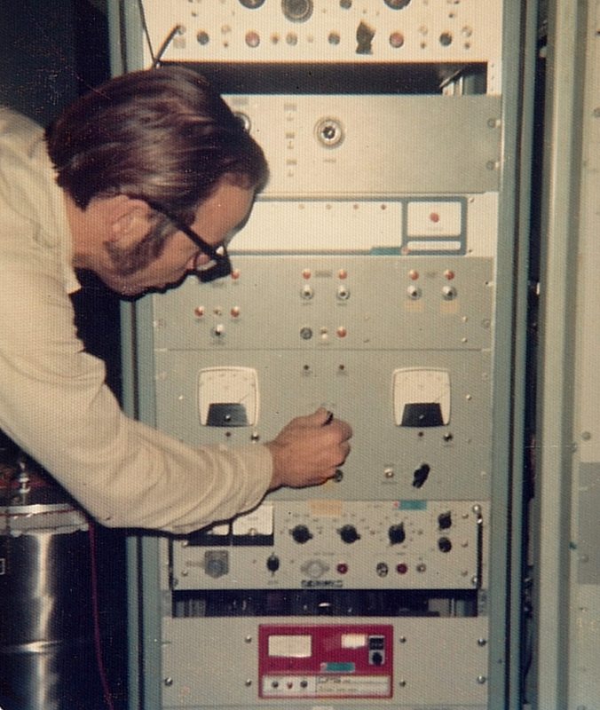
The author adjusting the Wampler Scanner electronics in 1974-5.
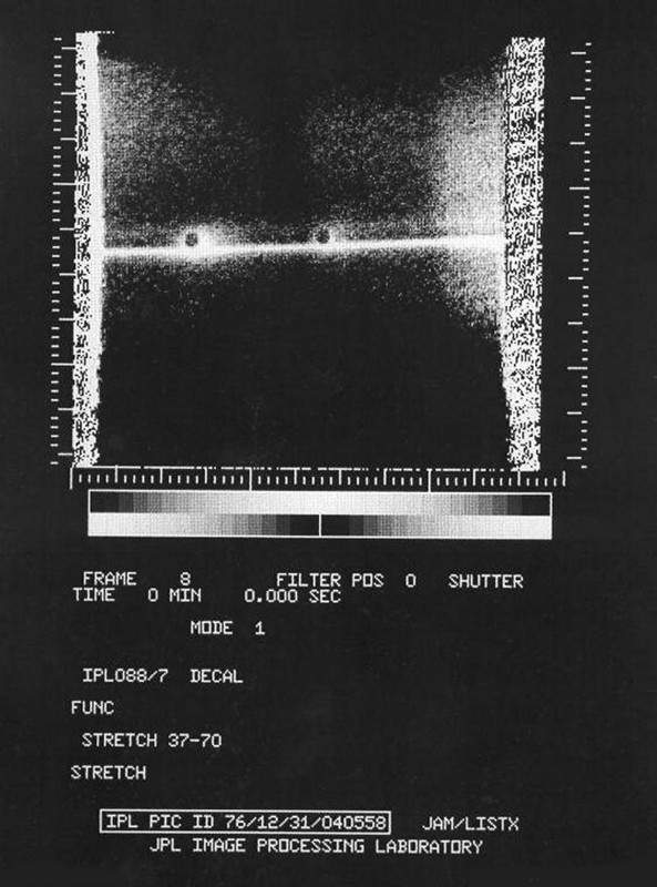
A 'raw' image taken from the SIPS instrument screen of the sodium D line emission in
December 1976.
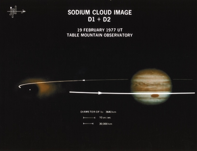
The result of the combined sodium D line emission, superimposed on an image of Jupiter,
with Io's orbit...all to scale. (1977)
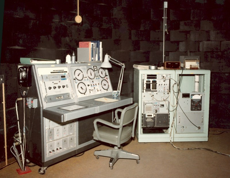
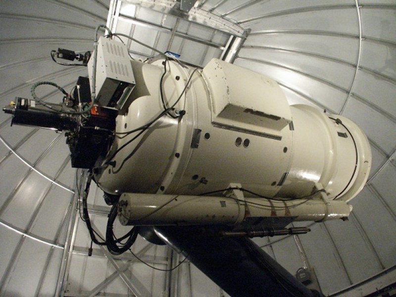
The full telescope and cassegrain instrument consoles for photoelectric photometry with the
photometer James Gunn built years earlier. (1980-91)
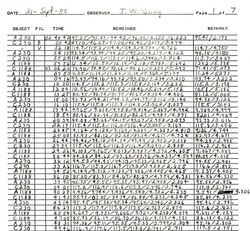
The actual log sheet made by the author during his asteroid observations of two different
asteroids; 230 Athamantis and 1188 Gothlandia on September 21, 1985. Pulse counting
readings are indicated in the 'READINGS' column...the first four are of the asteroid,
and the last two are of the sky for A230. The C230 readings are for the comparison
star used (with 4 star and 2 sky measurements). This is only one of 5 sheets made on
this particular night, which included 7 additional asteroids and comparison stars over a
period of 11 hours. (1985)
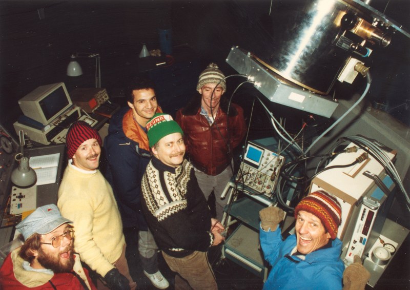
An excited group of JPL astronomers after a newly developed CCD camera was successfully
tested using the 24-inch telescope in 1988.
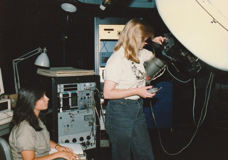
Two SURF (Student Undergraduate Research Fellowship) students making photoelectric
observations in 1988.
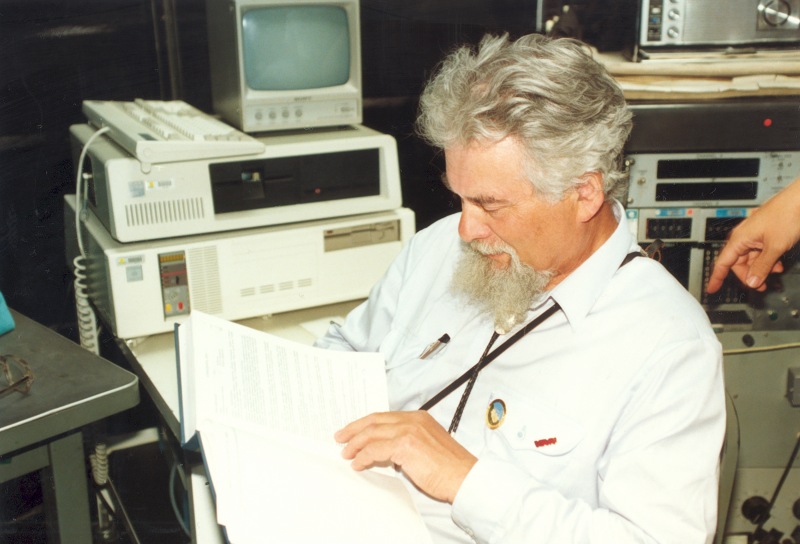
Viktor Shor of the IAA (Institute of Applied Astronomy - St. Petersburg, Russia) and a
member of the RAS (Russian Academy of Science) visited Table Mountain with Al Harris
in 1991.
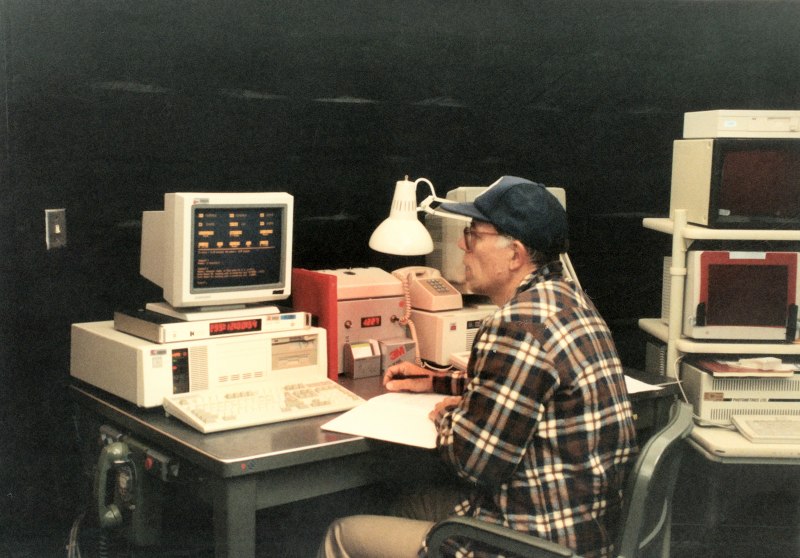
After contracting JPL's Ronald Dotson (computer programmer), he and the author developed
a operational program to run the old analog telescope system more efficiently. The original
telescope console was 90% eliminated by using two Everex 386 computers. All sky positions
were typed in and executed to move the telescope. (1991-92)
The entire 24-inch telescope was cleaned and repainted during 1992 in preparation for the
GOLD experiment.
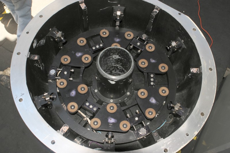
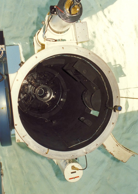
The 18-floating points of the 24-inch mirror cell were carefully checked to make sure they
were all level with each other. Three were not! One was 0.002 inches low and two were
0.001 inches high. All three points were on the same 3-point collar assembly. A 0.002-
inch shim was added to the low point, and the facility's machinist removed the 0.001-inch
overage from the two remaining high points. The result: most of the telescope's optical
visual astigmatism disappeared a week after the telescope/mirror cell was reinstalled and
realigned. (1992)
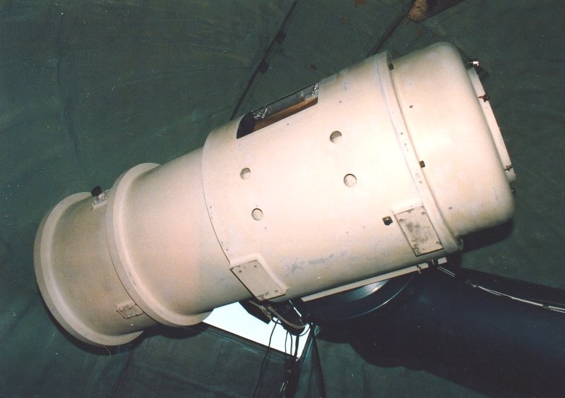
Repainting completed (1992)
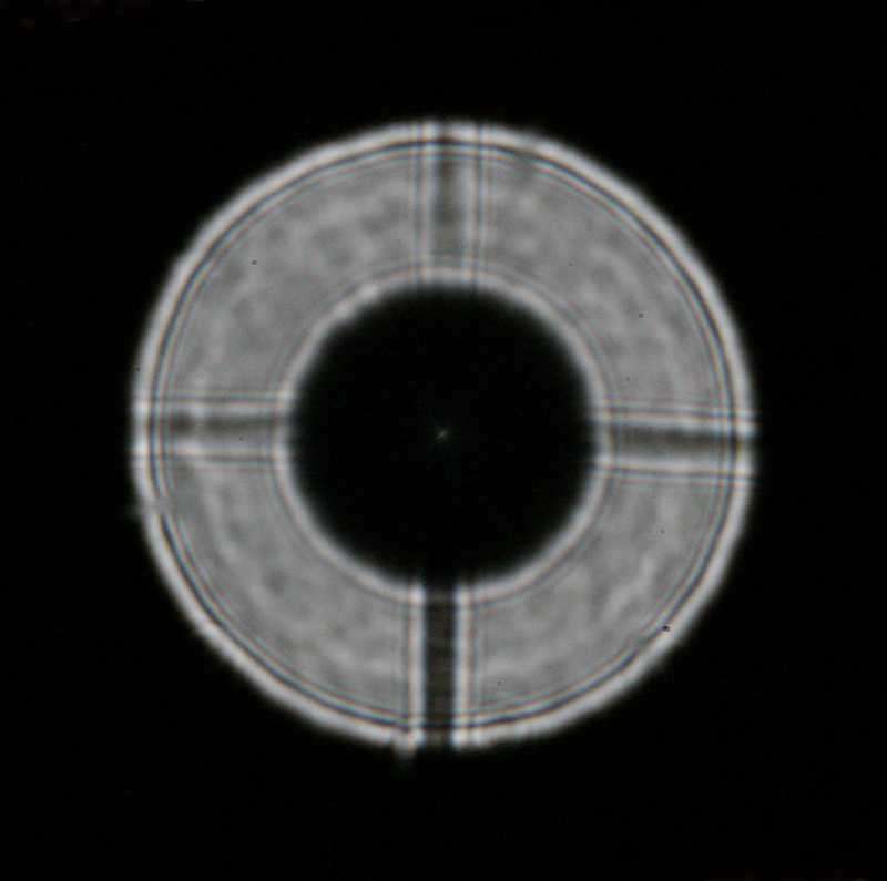
An out-of-focus image showing the excellent alignment (1992)
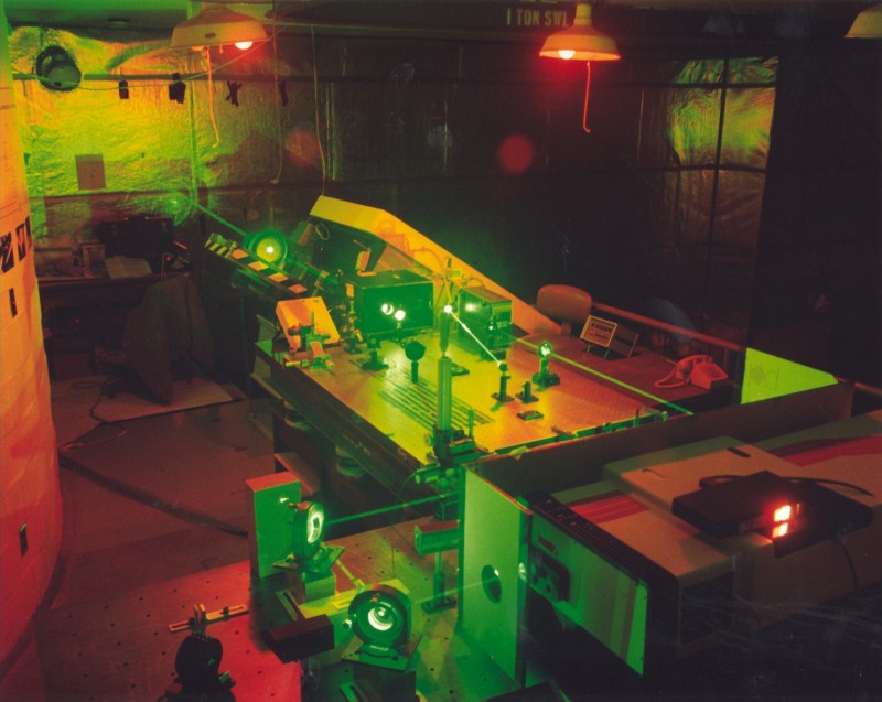
The GOPEX laser assembly set up in the upper coude room in late 1992, under the direction
of JPL's Keith Wilson. The focused laser path in the upper left, is entering the coude path
out toward its ultimate target...the Galileo Spacecraft some 6 million kilometers from earth.
(1992)
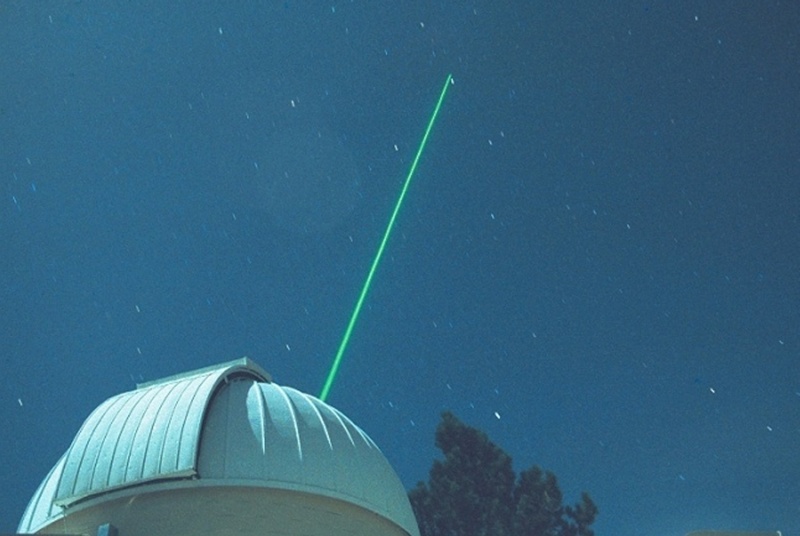
The laser path skyward (1992)
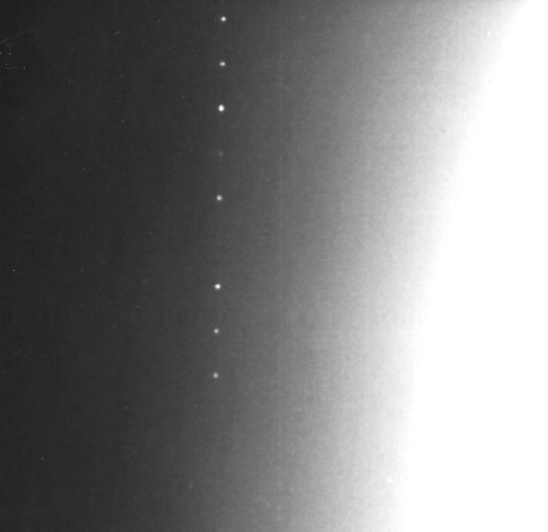
The bright spots (in a line) are the images of Table Mountain's laser as seen from the
Galileo Spacecraft's camera. The bright area to the right is the Earth's overexposed
image. The fourth image (fainter dot) from the top shows that the laser wasn't pointed
as accurately as with the brighter dots. In fact, the missing 6th dot shows the laser
missed the spacecraft completely! (1992)
GOLD (Ground/Orbiter Lasercomm Demonstration), another laser experiment in 1996, also
under Wilson's direction, was to point a similar laser toward the orbiting satellite ETS-VI
launched by the Japanese space agency, NASDA (National Space Development Agency of
Japan). Unlike GOPEX, this experiment was to send a laser beam to the satellite, which
in turn would trigger an onboard return laser back to Table Mountain's 48-inch telescope
in a round-trip communication link. This was successfully accomplished over a four month
period starting in late 1995. As with the 1968 Surveyor VII experiment, the author was
was the sole telescope operator for pointing/guiding in these three combined optical laser
experiment demonstrations.
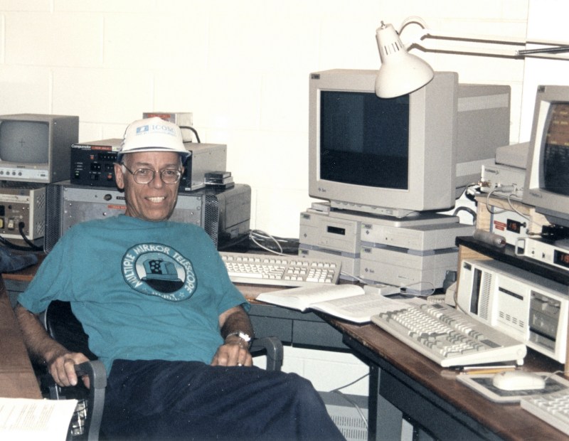
The author in the new control room (designed and furnished by Young) ready for his duties
for the GOLD experiment - January 1996
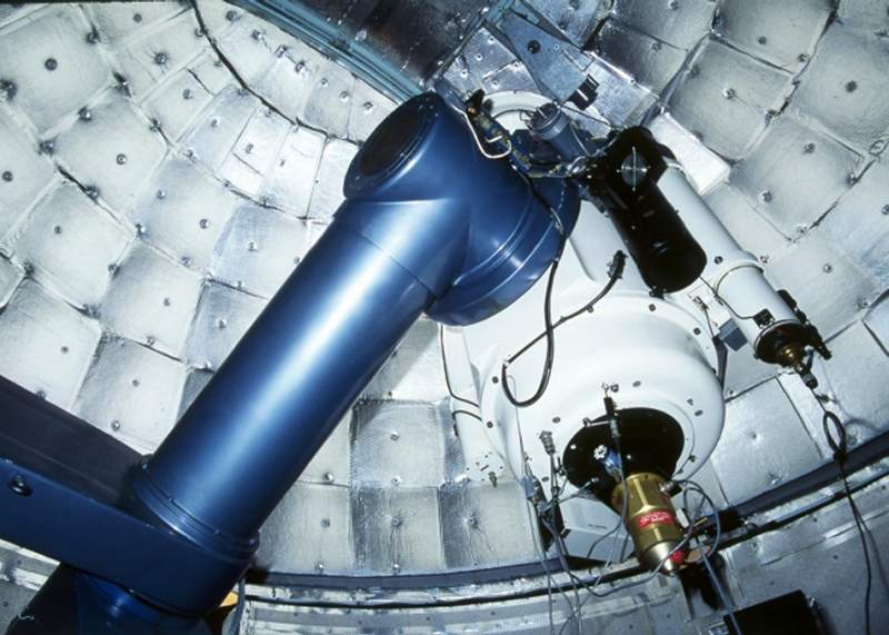
The GOLD laser beam exiting the 24-inch telescope... (1996)
After the retirement of Sandmann from Harvey Mudd College, another astronomer from the
same college acquired telescope time bringing a 500x500 pixel CCD camera into use by both
himself and others, including David Tholan and the author. This camera is seen here
mounted on the 24-inch telescope (lower left). (1996)
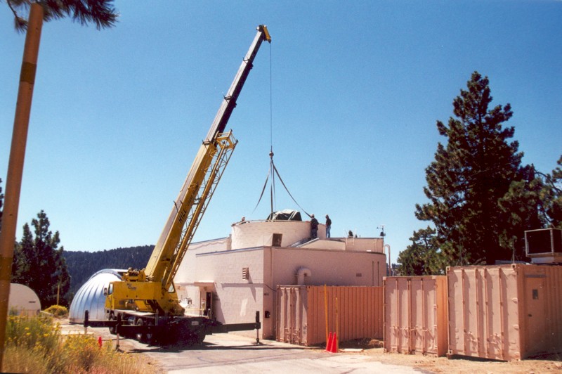
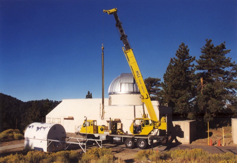
A new Ash Dome is placed on TM-12, the 24-inch telescope facility in 2001.
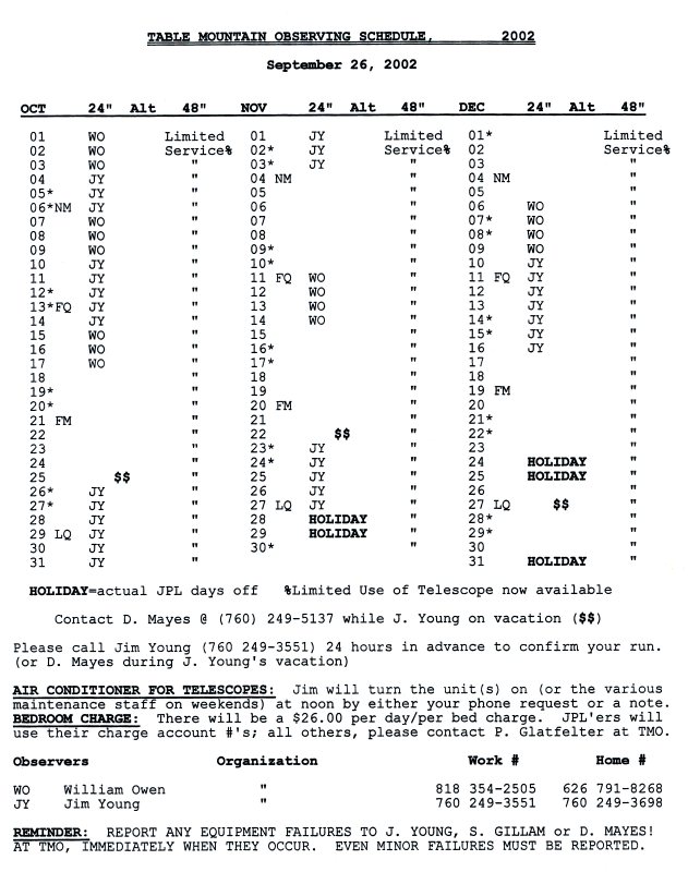
An example of the astronomy telescope schedule maintained by the author for his last 12
years at Table Mountain. This one dated for the fourth quarter of 2002.
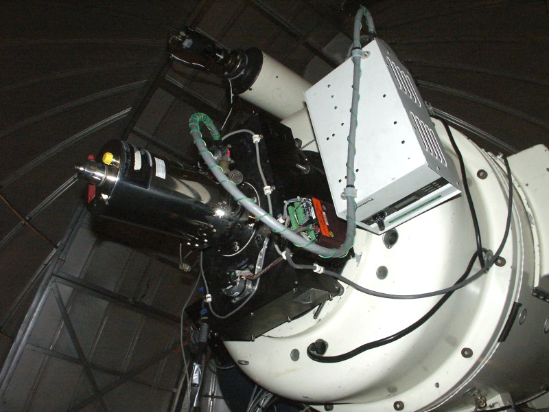
The astronomy group under Steve Gillam, the Astronomy Team Leader, acquired it's own
Photometrics (Tucson, AZ) 1k CCD camera in 1996. The author was given full charge to
make this camera as perfect for astronomy science acquisition as possible, including an
operational vacuum pumping station to keep it in top performance. The new CCD camera
(silver-colored tube device in the far left) is seen here mounted to a large black colored
filter box built by JPL's Michael Young (no relation to the author). (1996-97)
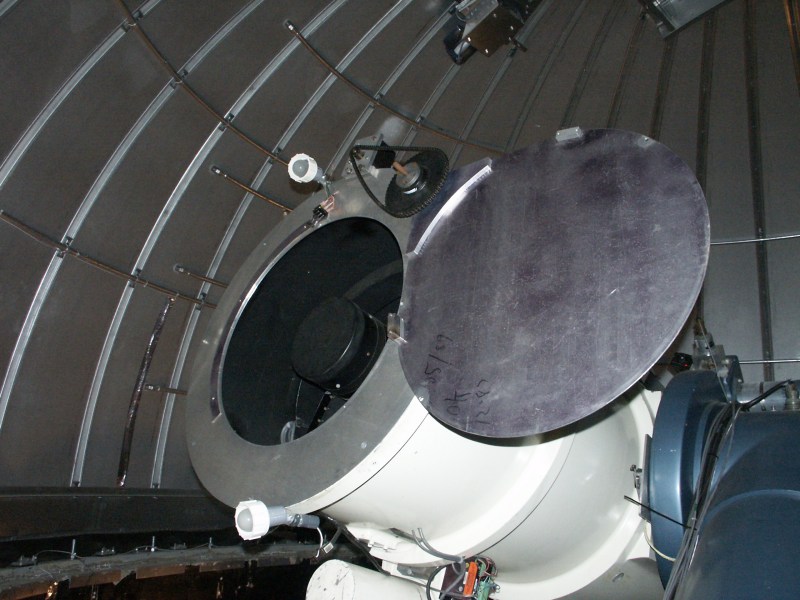
The author built this computer-controlled telescope cover for the 24-inch telescope in 1999.
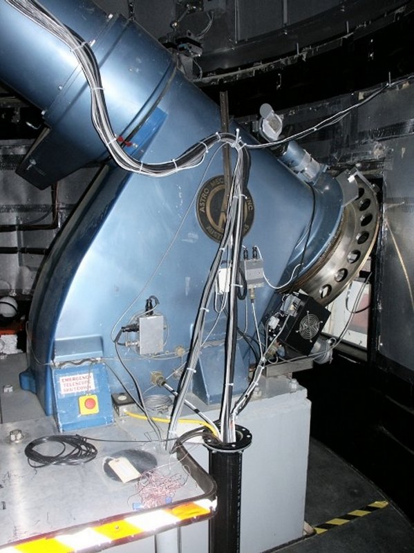
A new 40-inch diameter wheel was manufactured by Patford, placed symetrically over the
telescope's bull gear assembly. A Heidinhain steel tape was placed over the circumference
of this new wheel, with three Patford readers. This new modification gave to the 24-inch
a 75% increase in pointing/tracking accuracy. (2000)
Here is the Photometrics 1K CCD camera, power supply, and filter box assembly in 2004.
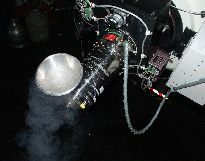
This was the method of filling the CCD camera with LN2. Usually the camera was filled
early in the afternoon (summer), and topped off 30 minutes before observing. This CCD
camera would last an entire summer night (6-8 hours). In the wintertime, the camera was
topped off once after midnight (for a full 11-12 hours).
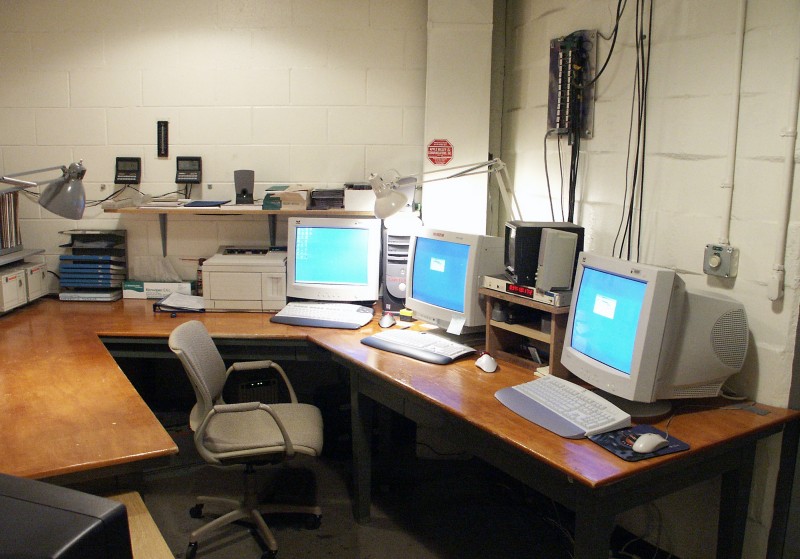
The 24-inch telescope control room in 2003.
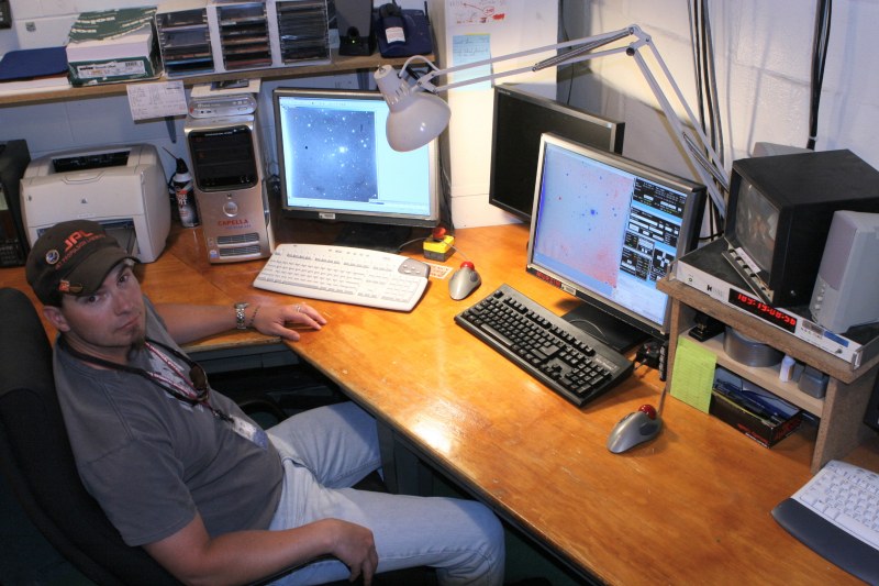
Heath Rhoades (Network administrator for the astronomy group) is seen here in the same
control room in 2008 after all CRTs were replaced with flat screens monitors.
End of Part 6A Part 6B